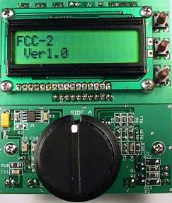
Image of prototype board/assembly
shown connected to the FCC-1
The FCC-2 is an addon to the FCC-1
Out of stock
Look for the revised FCC-2 Mk2
To be released soon
The NorCal FCC-2 is an add-on DDS VFO board that extends the basic capabilities
of the FCC-1 counter kit. All of the FCC-1 features have been retained, so
you won�t lose them by upgrading. A lot of work has been put into this kit
to minimize power consumption and permit battery operation for extended periods.
Surface mount technology (SMT) has been used extensively to minimize the size
and weight of the kit. The FCC-2 is peerless in its low power consumption and
flexibility.
The kit features a DC - 20MHz DDS (Direct Digital Synthesis)
chip, a shaft encoder and provides RTTY support. A new PIC microcontroller is
supplied with the kit, which adds the VFO to the basic counter features.
The VFO firmware supports 13 bands from 160m through 2m, plus a non-specific,
Direct band. There are numerous user-programmable parameters which are stored
in EEPROM for one-time setup convenience. You can easily switch between VFO
and frequency counter modes and the DDS output will retain its frequency.
You�ll see later on how we use this feature to calibrate the counter.
The user-programmable IF offsets and scale factors permit the VFO to operate
in a wide range of HF and VHF applications. The prescale feature permits
down-stream frequency multiplication or for use as a reference source for
a PLL synthesizer. The LCD displays the actual output frequency.
Dual VFOs and Split operation are supported in the firmware, and the FCC-2 will operate
RTTY straight off your workbench. Just connect a COM port cable and launch
the software. I�ve used MMTTY and it works great. You can incorporate the
FCC-1/2 combination into a homebrew rig or package them into a separate
enclosure for use as a portable test instrument. Typical current consumption
for the pair is less than 60mA. Operation is as simple as connecting a power supply.
If you ordered the FCC-2 kit with the DDS chip, it will be included in one of
the component bags. If you chose the lower cost option and haven�t yet ordered
the AD9834BRU sample from Analog Devices, point your browser to
Analog Devices . Search for AD9834 and scroll down the page to
order a sample. New users will need to register first, but it�s quick and
straightforward. Your new DDS chip will be in the mail shortly and best
of all, it�s totally free!
The kit contains all of the essential parts. All you need to supply are your
favorite pin headers. Over 90% of the components are SMT. To successfully assemble
the FCC-2, you need to have previous kit building experience, preferably with
SMT components. It�s not recommended that beginners attempt this project because
of its intricate nature. If you find yourself in over your head after purchasing
the kit, no problem. You can have the SMT components installed by Kit Builders.
Send Mike, WA6OUW, an email at wa6ouw@aol.com for further information.
It�s a good idea to read through the manual before beginning to get a better
understanding of the steps involved and the unit�s capabilities. You�ll find a
lot of useful information and application ideas in the following pages before
you warm up your soldering iron.
- Complete FCC-1 Frequency Counter support
- Shaft encoder for frequency entry, Memory and Menu mode operations
- 4 pushbutton and shaft encoder user interface
- Dual VFOs
- Split operation
- VFO copy: A-> B, B->A
- VFO can be band limited or full range
- Fast T-R switching
- FSK (RTTY) support
- 10 programmable frequency memories, store and recall to/from either VFO
- Last band frequency used is stored in EEPROM � after 30 second dwell
- Programmable transmit IF offset
- Programmable receive IF offset
- Programmable transmit frequency scaling: 1 to 255 - per band
- Programmable receive frequency scaling: 1 to 255 - per band
- Programmable transmit frequency calculation per band:
- Direct
- VFO+IF
- VFO-IF
- IF-VFO
- Programmable receive frequency calculation per band:
- Direct
- VFO+IF
- VFO-IF
- IF-VFO
- Programmable transmit RTTY Mark frequency offset � 2125 Hz nominal
- Programmable transmit RTTY Space shift frequency � 170 Hz nominal
- Programmable receive RTTY Mark frequency offset
- Programmable shaft encoder pushbutton function
- DDS Calibrate mode
- Extensive Menu mode
- Computer-controlled contest keying
| Dimensions | 1.5� x 3.0� x 1.25� (HWD) |
| Weight | 1.2 oz. |
| Power Requirements | 30 mA in addition to FCC-1. |
| Inputs | FCC-1 connection
RS-232 compatible FSK input: TXD, RTS, Ground |
| Usable Frequency Range | DC to >20 MHz |
| Outputs | 1. Lo-Z:
50 Ohm, 20KHz � 18 MHz output (-3dB)
3.0mw (4.7dBm) to 25mw (14 dBm)
@ 1MHz typ. Usable from 10KHz to 21 MHz.
2. Hi-Z:
600 Ohm, DC-18 MHz output,
580mVpp typical.
3.Key Out:
Active low, open collector, computer controlled via RTS |
| DDS Lowpass Filter | 7th order Elliptic |
| T-R turnaround delay | 1mS max |
| Frequency Memories | 10, user programmable |
| Band Memories | 13, frequency is automatically stored after 30 second dwell |
| Receive IF Offset | 0 to >268 MHz |
| Transmit IF Offset | 0 to >268 MHz |
| Receive Prescale Factor | 1 to 255, programmable per band |
| Transmit Prescale Factor | 1 to 255, programmable per band |
| FSK Mark Frequency Offset | 0 to >268MHz |
| FSK Space Frequency Offset | 0 to >268MHz |
| Supported Bands | 160m, 80m, 60m, 40m, 30m, 20m, 17m, 15m, 12m, 10m, 6m, 2m, Direct |
| Controls | Shaft Encoder with built-in pushbutton |
| Encoder Pushbutton | Programmable: Decade Increment, VFO A/B select |
|
FCC-2 Designer's Comments
|
I've been experimenting with several DDS VFO designs for a couple of years and
put everything I learned from those projects into the FCC-2, plus a few new
twists. I wound up designing a kit I wished were available 10 years ago. Many
of the ideas for the hardware were copied from my earlier designs. That was
the easy part.
The board design went through two prototype cycles before I was satisfied.
Then the idea of providing RTTY support came along. I hadn't thought about
it before, but it was so easy to include that another prototype was made.
Programs such as MMTTY work directly with the kit. A bonus for non-RTTY contest
ops is that the extra circuitry allows you to key the FCC-2 directly from a
computer COM port, so you can use your favorite contest program right away.
My goal was to make the FCC-2 as useful as possible, so audio frequency output
was mandatory. A separate unbuffered output is provided to allow you to use it
as a signal generator for testing audio amplifier stages and tweaking bandpass
filters. On the RF side, two amplifier stages provide plenty of drive for
high-level diode ring mixers or QRPp operation. One beta tester even hooked
the output to an antenna and had a few of QSOs with it. The DDS chip inherently
provides a low-distortion output and the 7th order elliptic low pass filter
removes the high order alias frequencies.
The firmware for the FCC-2 took a lot more time to develop. I didn't start
from scratch, but it was a real challenge anticipating all of the potential
applications and squeezing all of the code into a PIC with 4K of program memory.
All of the FCC-1 features were retained, and I think you'll like the new way
of programming the parameters using the shaft encoder. Above all, I wanted to
make it easy for you to use.
Programming the various frequency counter and VFO parameters is easy and
intuitive. The manual goes into great detail describing what they're used for
and how to set them up for your particular application. For starters, you can
use the FCC-1 & 2 as a bench-top frequency counter and signal generator, a
stand-alone VFO or incorporate them into a homebrew rig. I'm sure there are
many more.
Speaking of the manual, I think you'll be pleased with the step-by-step
instructions and numerous photos. A lot of effort went into eliminating any
guesswork. The FCC-2 was a fun project to develop and I hope you enjoy
building and using it.
I want to express my appreciation for the efforts of the beta testers Song
Kang, WA6AYQ; Bill Mabry, N4QA; Bob Miller, WB6KWT; Bill Phillips, AD6JV;
and Ron Smith, KE6RS. Your feedback was invaluable.
73,
Bob - W3CD
 FCC-2 Frequency Counter Controller Manual in PDF format (rev 1) FCC-2 Frequency Counter Controller Manual in PDF format (rev 1)
FCC-2 shipments beginning in June, 2006 use a new component kitting method.
Please use revision 2 of the FCC-2 manual for assembly instructions.
FCC-2 Frequency Counter Controller Manual in PDF format (rev 2)
|